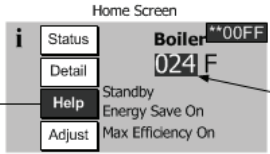
When the boiler enters into a hard or soft lockout the help button will be blinking. Anytime you see anything blinking on our display the flashing item should be pressed with the exception of items embedded in the Limit String and Sensor Status displays. These two displays will flash the problem limit or sensor. To access the proper troubleshooting screen follow the flashing buttons starting with the help button.
Using the Limit Sting Status Display
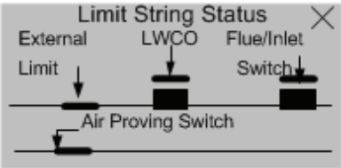
“The Limit String Status screen shows the safety limit status. A contact icon, either “open” or “closed”, graphically represents each safety limit. The “closed” contact icon is steady; the “open” contact icon is blinking. For example, the screen shown to the right illustrates a “closed” external limit contact and an “open’ LWCO contact.
NOTE: Since the limit string items are wired in series, all limits downstream of the “open” limit will also appear on the screen as “open” (blinking) icons regardless of whether or not they are actually open. The Air Proving Switch is wired independent to all other limits. The Air Proving Switch is only required to be closed during boiler pre-purge. It is normal for it to be open during run mode.”
Using the Sensor Status Display
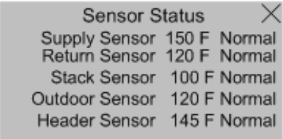
The Sensor Status screen shows the status of all sensors. Possible states include:
- None: Feature requiring this sensor has not been selected.
- Normal: Sensor is working normally.
- Shorted: Sensor is shorted or is defective.
- Open: There is a break in the wiring between the Control and the sensor or the sensor is defective
- Out of Range: Sensor is defective or is being subjected to electrical noise.
- Unreliable: Sensor is defective or is being subjected to electrical noise.
When a sensor fails “opened” or “shorted” the value is changed to reverse video (background black and value white) “024” or “768” respectively to indicate that there is a fault with the sensor.
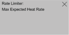
Using the Rate Limiter screen
The following messages appear when the firing rate is limited or reduced to help avoid a lockout or save energy.
Refer to Hard Lockout section for corrective actions
- High Stack Temperature Limit
- High Supply Temperature Limit
- High Differential Temperature Limit
The following messages appear as part of normal start and stop sequences:
- Minimum Modulation (normal start/stop sequence)
- Low Fire Hold Rate: Low fire hold rate is a normal start-up rate hold used to help ensure system temperature feedback prior to release to modulation.
- Low Fire Hold Time may be adjusted. Refer to the “Changing Adjustable Parameters”, Paragraph F , for additional information.
- Maximum Expected Heat Rate: Maximum Expected Heat Rate limit is a normal start-up rate hold used to save energy . This limit helps reduce extra cycles start-up rate hold used to save energy . This limit helps reduce extra cycles and save energy. Boiler is free to modulate up to the sum of the active zones and domestic hot water expected heat rates. Each zone heat rate is adjustable and may be modified under the modulation menu. Refer to the “Changing Adjustable Parameters”, Paragraph F, for additional information.
Using Energy Management System (EMS) Fault screen
The Energy Management System (EMS) fault screen provides input fault status. When an input is shown as “Not Selected” it is not required for this application or has not yet been selected. These options are selected under the “Energy Management” Adjust mode menu.
- Modbus Input Failure: If a modus input is selected and out of range or not present a “535” value is shown reverse video (background black and value white). To fix the problem check the input source and check that the input is properly connected.
- 4-20mA Input Failure: Failure status for the 4-20mA input is the same as shown under Sensor Fault.
